Hey folks, if you’re running an injection molding shop—whether you’re cranking out tiny plastic caps for soda bottles, automotive dashboard parts, or even medical device housings—you know how much rides on that robot working right. I’m Jake, I’ve been selling and supporting injection molding robots for 8 years, and let me tell you: bad calibration is the #1 hidden waste in this game. I’ve seen shops lose $10k+ in a month just because their robot’s arm is off by a quarter-inch, leading to bad parts, wasted resin, and hours of downtime fixing rejects. Injection Molding Robot

Today, I’m breaking down exactly how to calibrate your injection molding robot the right way—no fancy jargon, just stuff I’ve actually walked through with shop foremen across the Midwest. I’ll also throw in some pro tips from our team that you won’t find in a random YouTube tutorial, since I’m not just a random blogger—I’m the guy you’d call when your robot starts spitting out wonky parts at 2 a.m.
First, let’s get one thing straight: calibration here isn’t “tweaking a button” on your HMI. It’s making sure the robot’s coordinate system lines up perfectly with your injection molding machine’s, the tools you’re using (grippers, end-of-arm tools, EOAT), and the actual work envelope you’re trying to cover. A lot of new operators mix this up with “resetting the robot to zero”—that’s just the basics. Real calibration is step-by-step, and skipping even a step will come back to bite you.
Prep: What You Actually Need Before Starting
I don’t care if you’re using a 6-axis articulated robot, a linear servo robot, or a cobot paired with an injection machine—you can’t wing this. First, block off 90 minutes minimum (more if you’re doing a full calibration, not just a quick tune-up). Rushing this is how you get bad calibration. Grab these tools, no fancy lab gear required:
- A digital caliper (I use a 6-inch one, anything over 10mm accuracy works)
- A flat, rigid test block (aluminum is perfect—1x1x2 inch works, no warping)
- A reference point sticker (or a sharpie, but a vinyl sticker’s cleaner—make it a dot no bigger than a dime)
- Your robot’s HMI manual (not the one you skimmed when you unboxed it, the one with the calibration specs)
- A notepad to jot down numbers (don’t trust your memory—trust the notes)
Also, do a quick pre-check: turn the robot on, let it warm up for 10 minutes. Servo robots expand a little when they’re hot, so calibrating a cold robot will make it off once it’s at operating temp. Same with the injection machine—warm that up too, run a couple test shots to get it to its normal working temp. I can’t tell you how many times I’ve seen a tech calibrate a cold robot, then 2 hours later when the machine’s hot, the robot misses the mold because it shifted. That’s avoidable.
Step 1: Base Coordinate Calibration (The Foundation)
This is where most people mess up. Every injection molding robot has two coordinate systems: the robot’s own internal “world” (where it thinks its base is) and the molding machine’s “world” (where the mold is, the sprue pickup, the part drop-off). If these don’t line up, nothing else matters.
First, park the robot’s arm at a safe home position—one where it’s not near the mold or any moving parts. On your HMI, find the “calibration” menu, then select “base coordinate.” Now, you need to define three points: the robot’s base origin, the mold’s origin, and the pickup point.
Here’s the trick most guys miss: don’t just use the mold’s core for the origin. Use a reference point drilled into the mold plate itself. If you don’t have one, stick that dime-sized sticker on a flat, unused part of the mold (away from the cavity where parts form). Now, jog the robot’s tool tip (or test block) right on that sticker, and mark that as your mold origin.
Next, jog the robot to its base: stand where the robot’s mounting plate meets the floor, and drop a small mark there (the robot’s physical base origin). Jog the robot’s end-of-arm tool right on that mark, and input that as the robot’s base origin.
Wait for it—this step will prompt you for a third point, usually the direction of the X-axis. Just jog the robot 10 inches along the mold’s sprue line, jot that distance down on your caliper, and input it. This aligns the robot’s axes with the machine’s. I once had a shop skip this third point and ended up with the robot picking up parts sideways for a whole shift—total disaster.
Step 2: Tool Center Point (TCP) Calibration (The Make-or-Break Step)
This is the one that determines if your gripper actually grabs the part correctly, not just where the robot thinks it’s grabbing. I’ve seen shops with $50k robots mess this up because they just “estimate” TCP instead of calibrating it.
What’s TCP? It’s the exact point at the end of your EOAT—whether that’s a gripper finger, a vacuum cup, or a pin for inserting inserts. If that’s off by even 2mm, you’ll be picking up half-parts or dropping them into the wrong pocket.
For linear robots (the most common for injection molding), it’s super simple: put that aluminum test block on the mold’s origin point. Jog the robot’s tool to the exact center of the block’s top surface, then mark that spot. Now, jog the tool down 2 inches (your test block’s height) and mark that. Then jog it 2 inches to the right, mark that. The HMI will calculate the TCP from those three points. Done.
For 6-axis robots? A little more involved, but same idea: move the TCP to 5+ different fixed points on a reference surface, and the robot adjusts its kinematics. Pro tip from our team: if you have a vacuum gripper, use a small metal plate with a hole—jog the tool through the hole, that gives you a super accurate TCP. Avoid marking with sharpie—ink can smudge, and you’ll get a bad reading.
Step 3: Axis Offset Calibration (Fixing Drift Over Time)
Over time, robot axes shift a little—bearings wear, servo motors drift, especially if you’re running 24/7. This is axis offset calibration, and you should do this every 3 months, or after any maintenance (like changing a motor or gripper).
First, go back to that base coordinate we set earlier. For each axis (X, Y, Z, R, if it’s a 6-axis), jog the robot 1 foot along that axis, measure the actual distance with your caliper, and compare it to what the HMI says. If the HMI says 12 inches, but your caliper says 12.1 inches, that’s an offset of 0.1 inches. Input that into the axis offset menu.
Wait, don’t skip this step because it’s tedious. Last year, a regular customer of ours was running 100k parts a month, and their robot’s X-axis was off by 0.08 inches. They were throwing away 500 parts a week for 2 months before we told them to check axis offsets—cost them $8k in resin and labor. That’s a $20 calibration job that saved them thousands.
Step 4: Post-Calibration Test (Don’t Skip This!)
You can punch all the numbers into the HMI, but if you don’t test, you’re just guessing. This is the final check to make sure your calibration actually works.
Put a blank test mold (or if you don’t have one, use a small, simple mold you haven’t run in a week) into the machine. Set the machine to run a 10-second cycle, and set the robot to do: pick sprue, pick part, drop part into the bin. Run 5 cycles.
Check each part: is the part aligned correctly? Is the sprue picked every time? No missed grabs? If one cycle is off, go back to the TCP step—more than likely, you messed up that point. If it’s a whole axis, go back to axis offsets.
Pro move from our team: if you have a vision system paired with your robot (super common now for quality checks), run a quick test with that too. It’ll flag any tiny shifts you might not catch with a naked eye.
Common Calibration Mistakes I See All the Time
Let’s cut to the chase—here’s what I see guys do wrong that leads to bad calibration:
- Calibrating when the robot’s hot, then running cold parts: No, you need both robot and machine at operating temp. I’ve had a tech calibrate a robot, then come back 8 hours later when the plant’s empty, and the robot was off by a quarter-inch because it cooled down.
- Using a soft reference point: If your test block warps, or your sticker comes off mid-calibration, your numbers are garbage. Always use rigid aluminum, and tape the sticker down tight—double stick is better than single.
- Skipping the axis offset: I get it, it’s boring, but that’s why your robot drifts. If you don’t do it every quarter, you’ll be doing more rejects than production.
- Not adjusting for new EOAT: If you switch grippers (from 2-finger to 3-finger), or add a insert pin, you have to recalibrate TCP. One shop I work with changed their gripper and forgot to adjust TCP, so they started bending parts—cost them a new mold core.
When You Should Call Us (Not Try to DIY)
Look, 90% of calibration stuff you can do yourself with a little patience. But there are times where you’re better off calling a pro, and that’s where we come in. If:
- You have a 6-axis robot with a custom EOAT (not a standard gripper)
- You’re seeing consistent drift even after calibrating (that’s a mechanical issue, not a calibration issue)
- You need to calibrate for a new, large mold (bigger than 2ft, so reference points are tricky)
- You’re running a medical or automotive shop where bad parts = recalls (we do FDA-aligned calibration checks for those shops, no cutting corners)
We don’t just sell robots—we train your operators, help with calibration, and are on call 24/7 when you’re in a pinch. If you’re feeling overwhelmed, or you’ve tried calibrating and still have bad parts, hit us up. No weird hidden fees, no sales pitch that ignores your actual problem—just real support for injection molding robots.
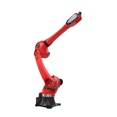
At the end of the day, calibration isn’t a one-time thing. It’s a routine, like changing your oil in a truck. Do it right, and you’ll cut rejects by 30%, save on resin, and keep your line running 24/7. Skip it, and you’ll be playing catch-up every shift.
Welding Robot References:
- “Injection Molding Robot Calibration Standards”, Industrial Robots Association, 2022
- “Preventative Maintenance for Injection Automation Systems”, Plastics Technology Magazine, 2023
- “TCP Calibration Best Practices for 6-Axis Robots”, RoboBuilders Inc., 2021
Robotic Technology (GD) Co., Ltd.
As one of the most professional injection molding robot manufacturers and suppliers in China, we have world-leading production equipment and strong manufacturing capabilities. Please feel free to buy durable injection molding robot for sale here from our factory. Also, custom service is available.
Address: Room 102, No.30, Hengfeng 2nd Road, Daguo, Changping Town, Dongguan City, Guangdong, China
E-mail: admin@iroboticplus.com
WebSite: https://www.rbtic-tech.com/
